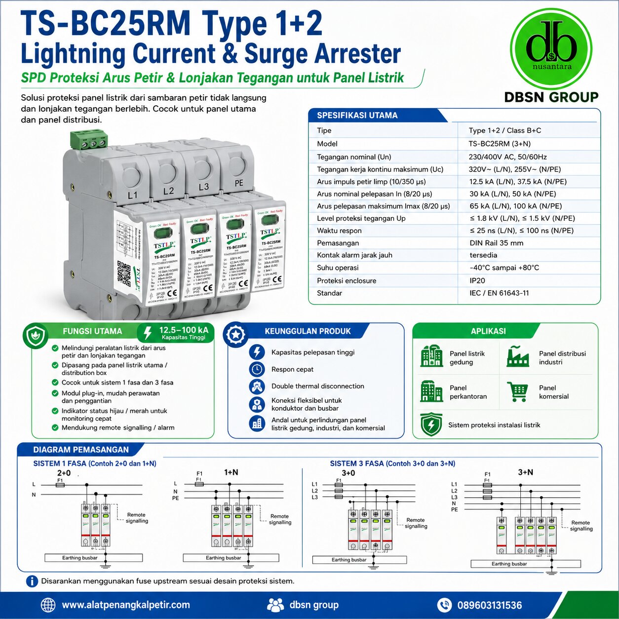
TSTLP®/TS-BC25RM Type 1+2 Lightning Current & Surge Arrester
TS-BC25RM series Type 1 lightning current & surge arrester, designed according to IEC / EN 61643-11 & GB 18802.11 is for installation at LPZ 0A -2 or higher, protecting low voltage equipment against lightning and surge damages. Applied SPD Modular in Class I+II (Class B+C) for various power supply system.
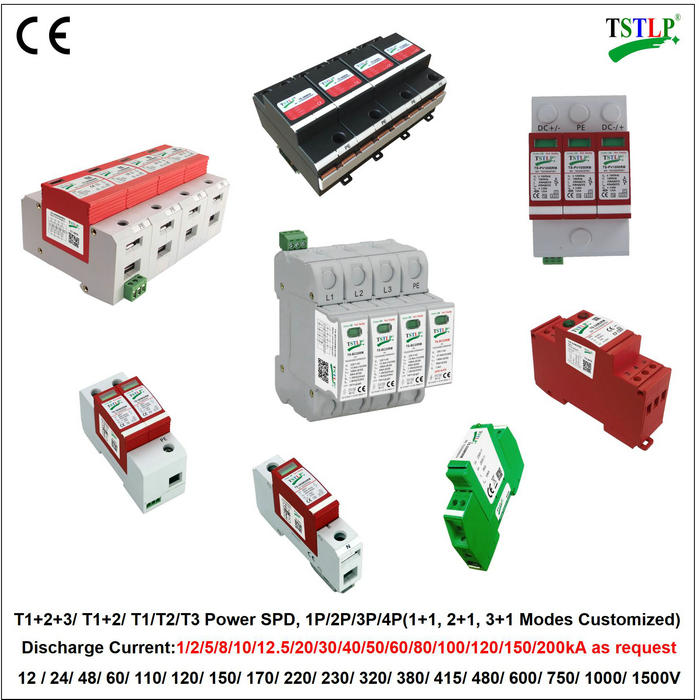
Similar & Related Power Supply Surge Protectors
Type 1+2 Lightning Current Arrester
Home » Lightning Products » Power Supply Surge Protection » Type 1+2 Lightning Current Arrester
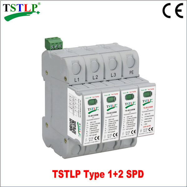
- Product Name :
TS-BC25RM(3+N) Class B+C Lightning Current & Surge Arrester

Previous : TS-385BC25/4 Type 1 & 2 Surge Protection
Instruction
TSTLP®/TS-BC25RM Type 1+2 Lightning Current & Surge Arrester
TS-BC25RM series Type 1 lightning current & surge arrester, designed according to IEC / EN 61643-11 & GB 18802.11 is for installation at LPZ 0A -2 or higher, protecting low voltage equipment against lightning and surge damages. Applied SPD Modular in Class I+II (Class B+C) for various power supply system.
Similar & Related Power Supply Surge Protectors
♦ Technical Data
| Type (1+2) | TS-BC25RM [ L/N] | TS-BC25RM ( N/PE ) | |
| Nominal voltage ( 50/60Hz ) | Un | 230V / 400~ | |
| Rated voltage (max. continuous voltage) | Uc | 320V~ | 255V ~ |
| Lightning impulse current (10/350) | Iimp | 12.5kA | 37.5kA |
| Nominal discharge current (8/20) | In | 30kA | 50kA |
| Max. discharge current (8/20) | Imax | 65kA | 100kA |
| Total discharge current | Itotal | 100kA | |
| Voltage protection level at @ 320V | Up | ≤ 1.8kV | ≤ 1.5kV |
| Residual voltage | Ures | 1.35kV @ Iimp | – |
| Follow Current | If | – | 1000A |
| Specific Energy | W/R | 39.06kJ/Ohms | 351.56kJ/Ohms |
| Response time | tA | ≤ 25ns | ≤ 100ns |
| Degree of protection (by the enclosure) | IP20 | ||
| Temporary Over-voltage Test Value | UT | 355V/5sec | |
| Number of ports | 1-Port | ||
| Installation Position Category | Inaccessible | ||
| Method of mounting | Fixed | ||
| Presence of Switching Component(s) | N-PE | ||
| Prospective Short-circuit current | 1A | ||
| Dielectric withstand | 3000V | ||
| Admissible Short-Current | Isccr | 25kA | |
| Orientation for normal installation | Indoor | ||
| Max. back up fuse [F] | 160A gL/gG | ||
| Operating temperature range [Tu] | Tu | -40°C…+80°C | |
| Cross-sectional area | 1.5mm2 ~ 25mm2 solid /35mm2 flexible | ||
| Mounting on | 35mm DIN rail | ||
| Enclosure material | Light Grey thermoplastic, UL94-V0 | ||
| Dimension | 1 mod | ||
| Standards | IEC 61643:11 & GB 18802.11 | ||
| Type of remote signalling contact | Switching contact | ||
| Switching capacity | UN/IN | AC:250V/0.5A; DC:250V/0.1A;150V/0.2A;750V/0.5A | |
| Cross-sectional area for remote signalling contact | Max. 1.5mm2 solid / flexible | ||
| Compliance | CE (LVD, EMC & RoHS) | ||
♦ MAIN CHARACTER
1. 10/350, 8/20ps varistors
2. Consist of varistor and thermal disconnection device
3. High discharge capacity, quick response, pluggable
4. Double thermal disconnection devices, providing more reliable protection
5. Multifunctional connection for conductors and busbars
6. Green window will change to red when fault and also provide remote alarm control at the same time
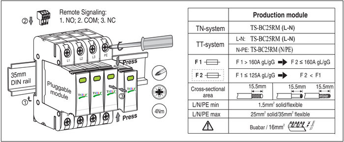
| INSTALLATION INSTRUCTION
According to lightning protection zones concept, for installation at LPZ 0A -2 or higher. It is usually installed in floor distribution-box or ClassⅠmain distribution-box Fuse must be installed at the upstream of the SPD or the surge protector to make sure that protected system has double protection. The value of the fuse used in a SPD system should be conformed to: 1. The value of FUSE should not be larger than the max.withstand capacity of the SPD’s backup fuse value. 2. Under the status of the max. current in the power supply & close loop circuit available current, the fuse should be able to disconnect when overloaded or short-circuited. Take 1 & 2 into consideration, the fuse should be as large as possible to allow the maximum surge discharge of SPD. |
| INSTALLATION STEPS
1) Check the product for integrity of the package; make sure the product window indicates green. 2) Mount the SPD on 35 mm DIN rail. 3) Connect conductors, the cross-sectional area of cable must be larger than 16mm2 . The withstand voltage value of cable is not smaller than AC500V; ensure wiring reliable. 4) If need remote alarm, it should be connected signal lines to remote signal terminal 1 and 2, or 2 and 3 (When normal,1 and 2 open, 2 and 3 close; when fault, the state is reversed). 5) Remote Contact: When the Green window display RED, 1 & 2 are connected; And the extra light will be on if the both terminals are connected with light. 6) After above, switch on the power supply and turn on the circuit breaker,if the SPD’s window does not appear red, this indicates the unit is operating normally. Regularly inspect the operating status, especially after lightning. Once the fuse upstream break, or the SPD’s fault appear, electrician should check/replace the SPD. |
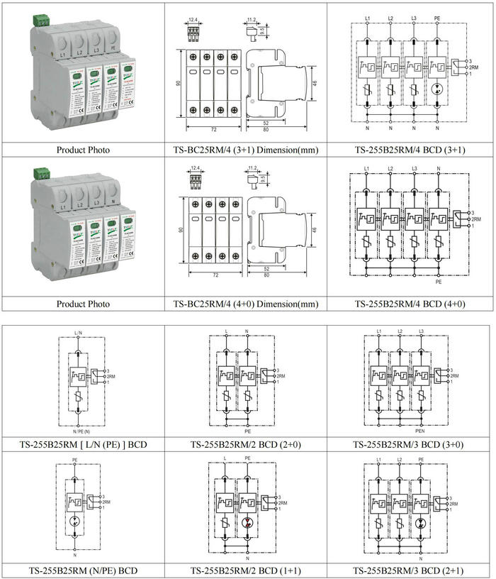
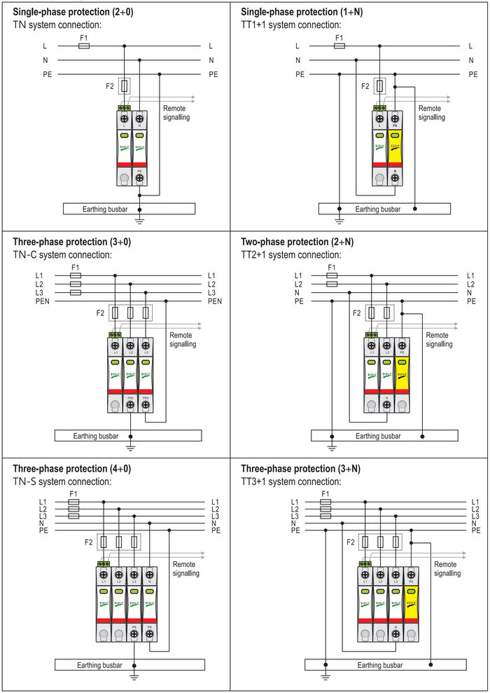
| INSTALLATION DIAGRAM (3+1)
|


Reviews
There are no reviews yet.